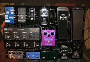
Pedalboard Rebuild – May 2012
Over the past week I’ve completed another full rebuild of my guitar pedalboard. This seems to be a once-every-18-months activity for me. Like Sisyphus, I have an endless repetitive task, all in the eternal quest for tone. I’ve been planning for this rebuild for a few months, and have been purchasing some new pedals. Given that I had a week without gigs, this seemed like an opportune time to commence the project and it gave me incentive to have it completed before beginning a new week of rehearsals.
Materials
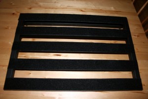
PedalTrain PT-3 pedalboard with flight case. I have been using PedalTrain boards for a number of years. They are well-designed, lighweight and very road-worthy.
VoodooLab PedalPower 2+ power supply. This power supply has eight isolated circuits that provide power to pedals. It is an industry standard. PedalTrain supplies brackets with each of their boards, making it very easy to mount this power supply underneath. I actually needed more than eight power feeds, so I soldered up a little splitter to provide 9v to two pedals from one of the circuits; ordinarily I’d be concerned about interference between the audio circuits. In this case there isn’t audio involved; the split circuit is feeding switch / control boxes with LED indicators.
Mission Engineering VM1 (version 2) volume pedal. I have a few pedals from Mission Engineering. This one is really pretty straight-forward as a volume pedal, but it also includes a tuner output and a switch (in toe-down position) that mutes the primary output for silent tuning. I don’t use the tuner output because this volume pedal is placed last in my signal chain; my tuner is actually at the front of my signal chain so I can tune without having to turn off effects.
- Sonic Research ST-200 strobe tuner. This was a recommendation from a friend. It’s a small and well-designed strobe tuner pedal that fits nicely on my board. I also have a Peterson StroboStromp2 tuner pedal but it’s quite a bit larger so it now resides in my music room.
- TC Electronic Trinity reverb pedal. TC Electronic reverb is beautiful and hugely dimensional. This little pedal is based on their “Hall of Fame” reverb, but has 2 additional presets. It is exclusively available via ProGuitarShop in Portland. This is a great store and I recommend you visit them online or in person.
- Xotic Effects EP booster pedal. This pedal emulates the preamp section of the Echoplex EP-3.
- Line6 G50 wireless receiver
- Line6 M9 multi effects pedal
- Dunlop Crybaby wah pedal – modified by Robert Keeley with the “Mello Wah / all mods” options.
- Way Huge Pork Loin overdrive pedal. This pedal falls into the same family of overdrives as the Tube Screamer or Sparkle Drive. It adds the right amount of grit and has a very useful blend function that dials in some of the clean tone for balance.
- Zvez Box of Rock distortion pedal. This pedal is designed to emulate the one of a cranked Marshall stack. It has a separate boost section that can be kicked in, which I rarely use.
- Keeley 4-knob compressor. This compressor pedal is so clean and transparent that it’s difficult to detect in use. It can be dialed in for a very dramatic “squish” tone if desired, but I use the optical compressor model in the M9 to get that heavy compression setting. The Keeley compressor is something I tap for a little more body in single-note bluesy solos.
- Switch Doctor channel switch for my Mesa/Boogie Lonestar. This is smaller than the stock Boogie footswitch and fits on my board much more easily. The two-button switch allows channel and boost selection. The Lonestar has two channels and I usually set up the lead channel with a little bit of drive, using the “tweed” option for the channel voice. The amp also has a built-in solo boost that can be remotely activated; I rarely use it, but occasionally it’s helpful to have a little extra wallop.
- Expression pedal switch box. This is a pedal that I designed and built myself. I purchased the components from Pedal Parts Plus and did the wiring myself. The Line6 M9 and M13 effect processors have two inputs for expression pedals. These inputs accept continuous controller pedals that provide a swept range from infinite resistance to 10K ohms. I wanted to have the functionality of switching between two parameter settings on a single effect, so I designed this simple circuit with a 3PDT footswitch to alternate between a dead short (ground and tip are directly connected) and 10K (provided by a 10K resistor), while turning on an LED for the 10K setting to indicate which position the switch is in. I built two of these circuits side by side in a small pedal enclosure. One of the footswitches is a momentary switch, handy for effects like my Leslie emulator; the rotation speed defaults to the slower setting but when I step down on this switch it speeds up to the higher setting, and releasing the switch spins it back down. Because the switch is momentary it’s much easier to manage effect settings that are frequently changed (I don’t need to click it down, let up, then click it again to reset to the original setting). I also use it for special effects that only are necessary for short phrases.
- Interface box. Another one I designed and built this one myself, using parts purchased from Pedal Parts Plus. The drilling and wiring was a challenge on this one because I wanted to use a small enclosure for it. It has a total of ten holes drilled in it: seven 1/4″ jacks, a DC input jack, a 3PDT footswitch and an LED. More information on this box in a moment…
The Build Process
The first step was to remove everything from the existing pedalboard. I’m reusing my trusty PT-3 so this project began by pulling off all the effects pedals, clipping the ties that bundled all the cables, and separating everything into little piles. My previous pedalboard configuration was largely dominated by my Line6 M13. In this new setup I’ll be using more individual effects, and it’ll also require a different power supply for all those pedals (see below for more specifics).
I always do a total de-lousing process when the pedalboard is stripped like this, so after some time with the shop vac I wipe down the entire board with alcohol to thoroughly clean it. Remember: pedalboards live on bar stages, which are infested with disgusting infectious things, such as musicians. Also, it seems like about once a year someone leans over onto the stage to tell me something and in the process gives my pedalboard a sip of their drink. Removing the sticky residue helps keep my toys clean.
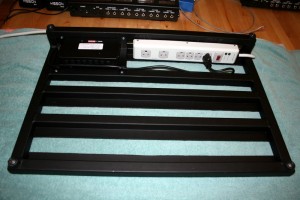
Step two is mounting the new power supply. There are many choices for a pedal power supply, but I’m partial to the VoodooLab Pedal Power 2+ since it has eight isolated power feeds for stable, regulated 9v output. Mounting the power supply under a PedalTrain board is very easy because the board ships with special brackets for this purpose. Once you mount the brackets on the power supply, it requires drilling four small holes into the pedalboard frame, and using the supplied self-tapping screws to finish the job. On the PT-3 board there isn’t a specific place along the back of the board where you are required to mount the power supply, so I moved it all the way to one side to leave space for the power strip which was necessary because two of my devices (Line6 M9 and Line6 G50 wireless receiver) have their own special transformers. The power strip acts as the main AC supply for the entire pedalboard, so the only thing shown plugged into it here is the Pedal Power 2+. However, it’ll have other things plugged into it once I start mounting pedals.
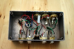
INTERFACE BOX
I like to have a single interface box where my pedalboard can be patched to the wired guitar input and various connections to the amp. It’s much easier to have these jacks in a box at the edge of the board, and saves wear on the effects jacks from repeated insertion and removal. For the rebuild of this board I had more connection points than before, so I took the opportunity to make a new interface pedal. It started with a blank enclosure and some very careful planning to get the jacks, switches, and LED all in places where they were on the correct sides of the box and still wouldn’t interfere with each other. Once it was all marked up, it took about 20 minutes with the drill press to get the holes drilled. I gave it a quick coat of enamel paint then did the assembly and soldering. It was a very tight fit, but everything works! The footswitch serves a simple purpose: switching between the wired and wireless guitar input signals. The LED is illuminated with the wireless feed is active. This might seem unnecessary, but it’s very helpful to know which signal is being fed downstream in the event something else isn’t working as expected.
Attaching the pedals to the board with velcro is pretty easy once you figure out where to put them. I usually start with Pedalboard Planner, a useful free online tool that can help you plan the layout of your board. It’s a handy tool but leaves out two important aspects of your board: the pedal height and the distance between pedals required for connectors. Because I use George L cables and connectors I know how much clearance to provide. When laying out this configuration I knew the two wah-shaped controllers would need slim-profile phone plugs in order to fit, so I soldered up four cables using slim connectors, attaching them to lengths of George L cable that I could trim and terminate once the board was laid out. In my initial plan for the board, I had intended to have the M9 at the front, with the Box of Rock and channel switch above it. But once I started to lay out the pedals I realized those two would be difficult to access given their height relative to the M9. As a result I switched the layout to put the Box of Rock and channel switch in front.
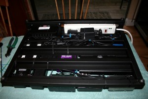
Here is a shot of the underside of the board with everything in place and wired. I’m a bit of a neat freak when wiring things up, bundling cables together and using cable ties to keep things tidy. I don’t want any cables to get snagged or nicked, and wherever possible I keep the audio and power connections apart. One important piece of equipment that isn’t shown here is a butane BBQ lighter that I keep handy when using plastic cable ties… when you clip the long tail off a cable tie, it leaves sharp corners that will inevitably find a way to poke your fingers when you pick up the board; I use that BBQ lighter to melt the end of the clipped cable tie.
Also visible in this picture are the two power supplies for the Line6 devices. I had to leave space along the power strip for the inline transformer that powers the M9, which is attached next to the power strip with a couple of cable ties.
BOARD FROM ABOVE
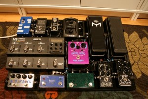
This is a shot showing the top of the board with everything in place. This shot is very nearly top-down so it’s difficult to discern the relative heights of the objects on the board.
Note how the wires are neatly bundled and out of harm’s way. I also make sure to leave a little extra space near the edges so the plugs are somewhat protected. When the board is inside its flight case, I don’t want any of the connectors to be damaged in transit. Troubleshooting a problematic pedalboard onstage is a nightmarish proposition, so I always put a lot of effort into testing every cable, plug and connection before assembly. Once the board is wired up, I do some jostle-testing on each connector to ensure everything is really solid and noise-free.
On first power-up I was rewarded with something beautiful: silence. The amp wasn’t producing any buzzing or humming of any kind. Once I started playing and stomping on pedals it was plenty louder in my music room 🙂 But it’s very satisfying to have the board generating zero background noise of its own.
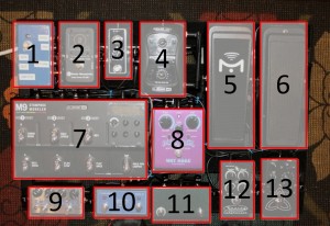
ID GUIDE
Here’s a handy guide to the items on top of the board:
(1) Interface box (2) Sonic Research ST-200 (3) Xotic Effects EP Booster (4) Line6 G50 receiver (5) Mission Engineering VM1 (6) Dunlop Crybaby (7) Line6 M9 (8) Way Huge Pork Loin (9) Zvex Box of Rock (10) Switch Doctor amp channel switch (11) Expression pedal (12) Keeley compressor (13) TC Electronic Trinity.
The signal chain goes thusly: guitar (either via wired or wireless input) -> interface box -> Sonic Research ST-200 -> Xotic Effects EP booster -> Keeley Compressor -> Dunlop Crybaby -> Way Huge Pork Loin -> Zvex Box of Rock -> Line6 M9 -> TC Electronic Trinity -> interface box ->amp
Update: Once I had a chance to run the board through its paces at rehearsals and a gig, I realized that the placement of the Line6 M9 was problematic in the sense that the pedals in front of it were taller than the front of the M9. It meant for some awkward gymnastics to access that device. The solution was pretty simple. My pedalboard is manufactured by PedalTrain, and they have an accessory called a “pedal booster” that adds a little extra height to make pedals easier to access. The M9 fits perfectly on the large version of the pedal booster, and neatly solved the problem.

